


A Tips and Tricks Tutorial By Rik Datta (“Rik” on
tg)
Creating illustrations with Only Extrudes
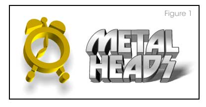
Xara’s Extrude tool has been with us for more than 4 versions, and although it’s a lifesaver when you need to dress up something in five minutes that’s visually bland, sadly a lot of us (myself included) don’t dig deeper into the possibilities of this tool just because we all know it extrudes shapes. Which leaves us with one of two possibilities, usually: either a cookie-cutter effect when you extrude a symbol font, or extruded text, as shown in Figure 1. Superman Comics used the now legendary extruded logo on their very first cover in 1939…so at best, extruded text has proven history, and at worst, it’s not as fresh as other graphics we see today.
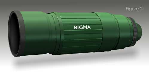
The long camera lens you see in Figure 2 uses the Extrude tool, believe it or not, and if you’re not a believer, download the zip file for this tutorial, go get a font (see Note below), and walk through these steps to follow. Because you need to use specific values and a special technique, most of this tutorial is presented in “recipe” style—as in “click here and do this”.
The principle of the lens construction will become evident as you work and you can indeed apply what you learn to building other things with the 3D tool. All you really need to remember is that if you take a circle and extrude it, it’s just a thick circle if you present it to the audience face-on, but if you rotate the extruded circle by almost 90 degrees top to bottom or side to side, you have a column…or the shaft to a bolt, or a chimney…or as you’ll soon learn…a long lens for a camera.
Gary Bouton had added a little something to the Xara file guide page you download—you can create a body for the camera with the pieces he’s added, and using rotations of the extruded object in specific, and perhaps unexpected, ways.
Putting Slot A into Tab B
You’re going to run through nine fairly detailed instructions in the parts to follow—let’s call them really long steps—and at the end, after you've created specific pieces for this long lens illustration, you’ll be shown, like in a bizarre IKEA instruction sheet, how the parts you've created are arranged together.
Let’s begin just a little before the beginning:
The Nudge Size in the Lens Cheat Sheet.xar document
you find in General Options (Ctrl+Shift+O) was set at
228px in a the document. This document is an exploded view of the
individual pieces as I created them for the very front of the
lens—after you’ve created 7 parts, I saw little reason in
making you create 7 more when the steps are essentially repetitive. To
reassemble the lens front as the finale to this tutorial, press the
Arrow Keys sequentially with each shape selected, Group the
pieces (Ctrl+G) and then press Ctrl+F to put the
group to the front of the page.
The second page of the Cheat sheet shows the completed illustration, plus Gary’s camera body you can add.
Many of the shapes are just larger versions of the original extruded shapes. However, once you “assemble” your lens, you will certainly feel like experimenting with the Rotation values just a little, or make minor alterations to the lighting.
Number the pieces after you create them or I’ll never be able to show you how they should be assembled! Once you’ve completed a section, type #1, #2, and so on next to the piece you’ve built.
That’s about it for a Prologue. To create the lens above, you’ll need to draw shapes (circles and thin rectangles), use the 3D Extrude Tool, choose a Bevel Type, and adjust the angles and lighting positions and colours. Follow along!
Building Piece #1
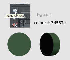
Draw a circle of 90px in size and colour it #3d563e, using the Color
Editor (Ctrl+E) and the Hexidecimal entry box at far right of the value
boxes while using either the HSV or RGB color models. With the circle
selected, choose the 3D Extrude Tool and then click the Apply Extrusion
button on the top left of the Infobar. From the Infobar—and
you’ll be entering precise values in this tutorial instead of trying
to drag on the shape with the Extrusion tool to attain precise values.
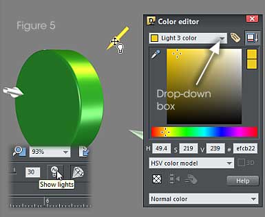
You need to set the Bevel type, the Bevel size, the amount of Angle 1, Angle 2 and Angle 3. You will also set the Extrude Depth, the Light Angle amounts for Light 1, 2 and three as well as the color of each light.
With the 3D Extruded circle still selected, please enter the necessary settings on the Infobar by work your way methodically through the following settings.
|
Piece #1 3D Extrude Parameters |
||
|
Bevel type to: Curve Faced 2 |
||
|
Bevel size: 60 |
||
|
Angle 1 = 3 |
Angle 2 = 52 |
Angle 3 = 3 |
|
Extrude depth: 30 |
||
|
Perspective: (default value) |
||
|
Light 1 Angle 1 = 14 |
Light 1 Angle 2 = -68 |
|
|
Light 2 Angle 1 = 57 |
Light 2 Angle 2 = 25 |
|
|
Light 3 Angle 1 = 101 |
Light 3 Angle 2= 21 |
|
|
Light 1 Colour = #3b4733 |
Light 2 Colour = #727a72 |
Light 3 Colour = #486b55 |
See Figure 4 for the results here.
Building Piece #2 (Second verse, same as the first!)
To get right down to it:
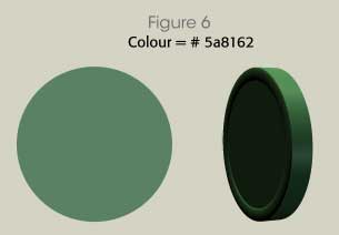
Draw a circle of 140px in size and colour it #5a8162. With the circle
selected, choose the 3D Extrude Tool, Apply extrusion and then make your
settings as listed below.
|
Piece #2 3D Extrude Parameters |
||
|
Bevel type to: Curve Faced 2 |
||
|
Bevel size: 60 |
||
|
Angle 1 = 3 |
Angle 2 = 63 |
Angle 3 = -3 |
|
Extrude depth: 15 |
||
|
Perspective: (default value) |
||
|
Light 1 Angle 1 = -64 |
Light 1 Angle 2 = -75 |
|
|
Light 2 Angle 1 = 107 |
Light 2 Angle 2 = -42 |
|
|
Light 3 Angle 1 = 72 |
Light 3 Angle 2= 11 |
|
|
Light 1 Colour = #c0e9a5 |
Light 2 Colour = #727a72 |
Light 3 Colour = #486b55 |
See Figure 6 to see what you just built, or
believe that you just built.
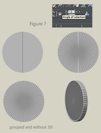
Ooooh! 3’s a fun part! Making a ring with grooves to twist!
This next set of moves will get you the attachment ring, sometimes the ring on one of these expensive things that helps attach and detach the lens from the camera mount. Follow along carefully; there’s no alarm clock set to go off in 20 seconds here at Xara Xone!
- Draw a
circle 139pxand colour it#9c9c9c. -
Draw a
vertical rectangle 2pxwide and141px highandcolour it #919191. -
Press
CTRL+SHIFT+Lto centralise both items using the Object Alignment box, by clicking in the center of the proxy box above the controls to put all the proxy objects horizontally and vertically centered. Then clickApply. - Press
CTRL+Kto clone the vertical rectangle, and then apply a5 degree angleusing the rotation box on the Infobar. You should carry on cloning and rotating by5 degreesuntil you have a complete set. With all the shapes selected,Ctrl+G(Group them). - Apply 3D Extrude using the Extrude tool.Then enter the parameters as seen in the Piece #3 Parameters table that follows.
|
Piece #3 3D Extrude Parameters |
||
|
Bevel type to: Round Faced |
||
|
Bevel size: 12 |
||
|
Angle 1 = 3 |
Angle 2 = 62 |
Angle 3 = -3 |
|
Extrude depth: 9 |
||
|
Perspective: (default value) |
||
|
Light 1 Angle 1 = -98 |
Light 1 Angle 2 = -6 |
|
|
Light 2 Angle 1 = -9 |
Light 2 Angle 2 = -73 |
|
|
Light 3 Angle 1 = 49 |
Light 3 Angle 2= 16 |
|
|
Light 1 Colour = #898989 |
Light 2 Colour = #7c7c7c |
Light 3 Colour = #383a39 |
Figure 7 shows a pretty groovy addition to the long lens.
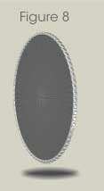
Part 4: Using a Bevel Preset as a Visual Element
This part of the lens gets its character from the type of bevel you use. The Rounded Corner 1a puts very small rings at both ends of the extrude, but ordinarily you wouldn’t notice them unless you have your extrude positioned at about a ¾ angle as you’re doing in this tutorial:
- Clone the Circle in Part 2. We’re talking the base circle and not the extruded shape, so you can right-drag the #2 part to a different location on the page and then release the right mouse button to accomplish the duplication (the clone). Then you remove the Extrusion by clicking the 3D icon at the left of the Infobar when the shape is selected with the Extrude tool, and the object returns to 2D.
- Scale its size up to
146px. Apply 3D Extrude, then chooseBevel type Round Cornered 1afrom the drop-down list, and change the Bevel size to 15.- Adjust the Extrusion parameters as follows (I think you’re getting the hang of this part now!):
|
Piece #4 3D Extrude Parameters |
||
|
Bevel type to: Rounded Corner 1a |
||
|
Bevel size: 15 |
||
|
Angle 1 = 3 |
Angle 2 = 63 |
Angle 3 = -3 |
|
Extrude depth: 15 |
||
|
Perspective: (default value) |
||
|
Light 1 Angle 1 = -64 |
Light 1 Angle 2 = -75 |
|
|
Light 2 Angle 1 = 105 |
Light 2 Angle 2 = -44 |
|
|
Light 3 Angle 1 = 69 |
Light 3 Angle 2= 10 |
|
|
Light 1 Colour = # c0e9a5 |
Light 2 Colour = #727a72 |
Light 3 Colour = #486b55 |
See Figure 8.
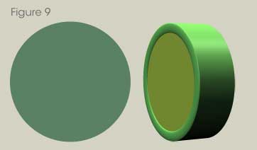
Part 5, an Easy One
Clone the 3D shape that is Part #3, and all you have to do is to change
the Extrude depth to 1. Finito, done-ski, see Figure
9.
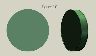
Part 6: Revenge of the Extrude Tool
In the continuing saga of the Clone Wars, your next step is to clone the circle Part #4.
- Scale the circle to
170 pixels. - Apply 3D Extrude, and use the Bevel type called
Curve Face 2from the drop-down list on the Infobar. This is a neat preset—it carved a small interior to the extrude, perfect for creating a lens or a machined object. - Make the
Bevel Size 60. - You got it—adjust the Extrusion parameters as so…
|
Piece #6 3D Extrude Parameters |
||
|
Bevel type to: Curve Faced 2 |
||
|
Bevel size: 60 |
||
|
Angle 1 = 3 |
Angle 2 = 63 |
Angle 3 = -3 |
|
Extrude depth: 35 |
||
|
Perspective: (default value) |
||
|
Light 1 Angle 1 = -64 |
Light 1 Angle 2 = -75 |
|
|
Light 2 Angle 1 = 60 |
Light 2 Angle 2 = -69 |
|
|
Light 3 Angle 1 = 75 |
Light 3 Angle 2= 9 |
|
|
Light 1 Colour = #c0e9a5 |
Light 2 Colour = #727a72 |
Light 3 Colour = #486b55 |
See Figure 10.
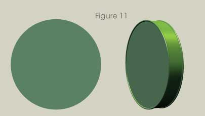
Building Part 7: You’re almost there!
- Clone (
Ctrl+K, or use the “drop a copy” technique) the circle used for Part #6. Return this copy to its 2D state by unclicking the 3D Extrude button at left on the Infobar. - Resize it to
178.5px. - Apply 3D Extrude,
Bevel type Round Cornered 1, and then set theBevel size 12. - Adjust the Extrusion parameters to these exacting and mission-critical values:
|
Piece #7 3D Extrude Parameters |
||
|
Bevel type to: Round Cornered 1 |
||
|
Bevel size: 12 |
||
|
Angle 1 = 3 |
Angle 2 = 60 |
Angle 3 = -3 |
|
Extrude depth: 17 |
||
|
Perspective: (default value) |
||
|
Light 1 Angle 1 = -64 |
Light 1 Angle 2 = -75 |
|
|
Light 2 Angle 1 = 60 |
Light 2 Angle 2 = -69 |
|
|
Light 3 Angle 1 = 77 |
Light 3 Angle 2= 9 |
|
|
Light 1 Colour = #898989 |
Light 2 Colour = #7c7c7c |
Light 3 Colour = #383a39 |
Watch Figure 11. It moves if you shake your monitor up and down.
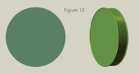
Part #8: Almost like Part 7
- Clone the circle in Part #5 and then unextrude it, exactly as you did with Part #7.
- Resize the circle to
178.5px. - Apply the 3D Extrude, choose the
Bevel type Round Cornered 1, and then set theBevel size 12. - Adjust the Extrusion parameters to these values:
|
Piece #8 3D Extrude Parameters |
||
|
Bevel type to: Round Cornered 1 |
||
|
Bevel size: 12 |
||
|
Angle 1 = 3 |
Angle 2 = 63 |
Angle 3 = -3 |
|
Extrude depth: 17 |
||
|
Perspective: (default value) |
||
|
Light 1 Angle 1 = -64 |
Light 1 Angle 2 = -75 |
|
|
Light 2 Angle 1 = 60 |
Light 2 Angle 2 = -69 |
|
|
Light 3 Angle 1 = 72 |
Light 3 Angle 2= 9 |
|
|
Light 1 Colour = #3b4733 |
Light 2 Colour = #727a72 |
Light 3 Colour = #486b55 |
Voila! See Figure 12.
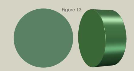
Number 9, Number 9, Number…
Next up after Part #9 is to assemble what you’ve built so far. So without further adieu…
- Clone the Part #6 shape, remove the extrude so you’re left with
a circle, and then resize it to
196.5px. - Click that Apply 3D Extrude button now, and then change the
Bevel to
      Rounded
, at avalue of about 12on the Infobar. - Apply the following settings on the Infobar (you’ve done this a few times before!):
|
Piece #9 3D Extrude Parameters |
||
|
Bevel type to: Rounded |
||
|
Bevel size: 12 |
||
|
Angle 1 = 3 |
Angle 2 = 63 |
Angle 3 = -3 |
|
Extrude depth: 41 |
||
|
Perspective: (default value) |
||
|
Light 1 Angle 1 = -64 |
Light 1 Angle 2 = -75 |
|
|
Light 2 Angle 1 = 60 |
Light 2 Angle 2 = -69 |
|
|
Light 3 Angle 1 = 78 |
Light 3 Angle 2= 9 |
|
|
Light 1 Colour = #c0e9a5 |
Light 2 Colour = #727a72 |
Light 3 Colour = #486b55 |
See Figure 13.
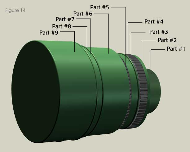
Assembling a Long Lens
Oddly, this tutorial gets much easier now at its final stages, not harder. You’ve numbered the parts, you have them all in a convenient location on the page or spread, the next thing you want to do is purely visual—it requires very little text explanation here. It’s important to position them as shown here, so as to create the correct effect of the various lens parts. Rely on Figure 14 and the Selector tool to make it all happen for you.
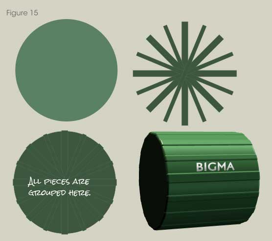
Creating the Focal Ring
This is the widest, largest part of the lens assembly and it has the fictitious name of a manufacturer on it, in case someone with a camera wants to take a picture of your camera (?).
- Create a Circle of
209px in diameter. Give it the colour of#5a8162. - Draw one vertical rectangle
13px wideand212px highwithline width of 0.25px. Give the line colour#5a8162. The line colour ultimately determines the colour of the extruded side of the object. This is why you really can create gradients and such on the extruded side of a Xara Extrude shape. - Draw another vertical rectangle
8px wideand212px highwith line width of0.25px. Give the line colour#5a8162. - Clone the thicker rectangle and rotate it
45 degrees,3 times. - Clone the thinner rectangle and
rotate it 22.5 degrees, and then clone that one androtate 45 degrees, 3 times. - Position all rotated pieces, as shown and then bring up the Object
Alignment box (
CTRL+SHIFT+L) and then with all the pieces selected, center them. - With all pieces selected,
CTRL+Gto group them. - Position these over the circle and centralize them all.
- Group all these pieces together, so you have a group within a group.
- Choose the
Bevel type Rounded, and aBevel size of 28. See Figure 15.
The ring isn’t as long as we’d like it to be, and as before (many times) you need to set other parameters on the Infobar for the object:
|
Creating the Focal Ring 3D Extrude Parameters |
||
|
Bevel type to: Rounded |
||
|
Bevel size: 28 |
||
|
Angle 1 = 3 |
Angle 2 = 68 |
Angle 3 = -3 |
|
Extrude depth: 102 |
||
|
Perspective: (default value) |
||
|
Light 1 Angle 1 = -70 |
Light 1 Angle 2 = -77 |
|
|
Light 2 Angle 1 = 102 |
Light 2 Angle 2 = -54 |
|
|
Light 3 Angle 1 = 62 |
Light 3 Angle 2= 10 |
|
|
Light 1 Colour = # c0e9a5 |
Light 2 Colour = # 727a72 |
Light 3 Colour = # 43704d |
Finally, add any sort of text you like to the side of the focus ring.
Putting the Xara Cheat Sheet to Work
If you’d like a quick finish to this tutorial so you can go out and take some pictures, here’s the skinny on making the complete lens illustration:
- Copy the back of the lens (the 9 grouped pieces you did at the beginning of this tutorial), and the focal ring.
- Open Xara Cheat Sheet.xar, and then paste the two grouped shapes into
the page. See Figure 16.
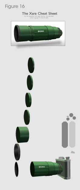
- Move the pieces over so you have a clear view of the seven shapes on the page.
- Group the focal ring and the lens back parts, and align them to the right of the last part at the bottom of the page. Use the guideline I dragged out to align the respective part bottoms.
- Select the first part at the top of the page. Nudge it down by one keyboard keystroke.
- Group it with the lens part to the left of it.
- Repeat steps 5 and 6 until your composition is complete. You might choose to put a feathered drop shadow beneath the work to make it look fancier, and Gary has provided the camera body parts both posed in 3D and as 2D objects, so don’t say you have nothing to do on the Xara Xone this month!
Enjoy, and I’d love to hear some feedback on The Xara Xone area of TalkGraphics.
About Rik Datta
Be sure to thank Rik for this great tutorial by showing us your 3D illustrations in the Talkgraphics.com thread, September 2014 Tips and Tricks: Creating illustrations With Only Extrudes.

(Rik online), TalkGraphics Moderator and member since 2009, says that he has learned the most from other members. Although Rik doesn’t use Xara Designer directly in his job—but rather for personal pleasure, he has used the world’s fastest drawing program to help visualize concepts, flowcharts, and other training collateral material for his 9 to 5 tasks.
Instinctively curious about how the work of others is produced, Rik has quickly become a valued resource on TG for logo design and a slick, sometimes reflective material rendering that has become instantly recognizable by fellow members.
The tutorial Creating illustrations With Only Extrudes including the artwork and the downloadable examples file are Copyright © 2014 Rik Datta. All Rights Reserved.